ViragoTechForum.com :: Yamaha Virago XV Forums That Rock!!!

ViragoTechForum.com Tech Articles relay & cycom elimination on 1982 920

#1:  relay & cycom elimination on 1982 920 Author: geo Post Posted: Sat Jan 13, 2007 2:33 pm

Removal of Starter Cut-Off Relays For 1982 920 Virago. By geo from viragotech.com. now called viragotechforum.com


Warning!!! This is a custom chopper mod only!! Eliminating these will cause your start button to be active at all times. If you press the start button while the motor is running, it will still try to start it!! Also you can ride off with the side stand down!!

This is the process to remove the side stand switch, clutch switch, isolation diode, starter cut-off, starter cut-out, side stand relays, and their associated wiring. This makes for a simpler and neater wiring harness and the need to find a place to stash the relays.
I had my wiring harness out on the table and removed the wrapping on the harness. This made easy work of pulling wires no longer used from the harness. It also is a good time to check the other splices in the harness. There are eleven splices in the main harness from the factory!

1) We will start inside the headlight.

Find the small, white 9-pin connector coming from the cycom. Clip the green wire with the blue stripe ( Cut it long enough to ground it. You will ground the wire coming from the cycom, as you are fooling it into thinking the side stand is UP! ). It is the one next to the white w/red stripe. DO NOT clip the plain green wire!!
This will keep the "stand" icon from showing up on the cycom and keep the "warning" light from lighting or blinking.
I plan on writing another article to eliminate the cycom in the near future as a companion to this one so you can scrap the cycom also.


Remove the clutch switch by inserting a small screwdriver in the small access hole to release the tab holding the switch in place. Trace the wire to the green 2-pin connector. Clip both wires on the main wiring harness side of the connector. You may be able to pull the wires through the harness from under the seat.


2) Under the seat

Remove the seat. Remove the side stand switch. At the side stand switch connector (white 3 pin connector with black, blue w/yellow stripe, green w/blue stripe wires) find the green w/blue wire. This runs to the front where you clipped it earlier. You may be able to pull it through the wire harness.

Find the blue w/yellow stripe wire. It goes to a splice in the main harness approximately 5 inches from the connector. The single wire going to the front is one of the clutch switch wires you clipped earlier. You can try and pull it out of the harness. Find the wire going from this same splice that goes to the diode. On the other side of the diode, the wire is sky blue. Approximately 5 inches from the diode is a splice. There are 4 wires spliced here. You want to clip the wire going to the diode and the one going to the starter cut off relay. The two that you want to keep connected are the ones going to the neutral switch and the one going to the front in the main harness to the neutral light.

There are three relays mentioned in the beginning of this article. All 3 are gold colored and say "OMORON" on them. The two with the number "4U8-00" printed on them and have blue connectors. The other has a white connector and has "4H7-01" printed on it. You will note there are several red w/white stripe wires jumping back and forth between the relays. On the relay with the white connector, 2 of these go to the other relays, the other goes to the main harness and goes to the RUN/STOP switch on the right handle bar. Clip this wire, you will connect it to the next wire you will clip so you can judge how long to clip the wire. Find the relay with the blue connector and with the 2 red w/white, black and white w/yellow stripe wires.
Clip the red w/white wire that goes into the main harness. This wire goes to the starter solenoid. Splice the two wires you just clipped. On that same relay, find the white w/yellow wire and trace it to a splice approximately 4 inches from the relay and clip it from the splice. This wire connects the control unit, cycom and relay. It is what some believe to be the tach signal, which could energize the relay and shut the starter down once the engine has started. Find the black wire on the same relay and trace it about 4 inches to a splice and clip from the splice.

At this point, there is only one relay left connected. This relay has 2 wires we need to clip. Find the black wire that goes to the same splice we clipped a black wire for the previous relay. Clip this one also. The black w/white stripe wire is the ignition cut-out if you leave the kickstand down and put the bike into gear. You can either clip it here, or clip it at the TCI 6 pin white connector and pull the excess wire from the main harness. You are now finished!

Warning!!! This is a custom chopper mod only!! Eliminating these will cause your start button to be active at all times. If you press the start button while the motor is running, it will still try to start it!! Also you can ride off with the side stand down!!

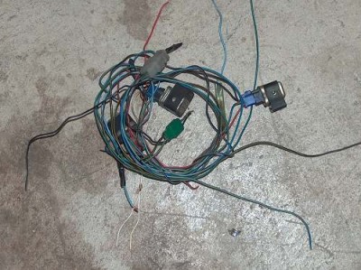
This, plus the side stand switch and clutch switch is what you have eliminated form the wiring harness.


removed_wiring.jpg
 Description:
 Filesize:  38.8 KB
 Viewed:  65 Time(s)

removed_wiring.jpg


Last edited by geo on Thu Oct 30, 2008 6:38 pm; edited 7 times in total

#2:   Author: Spindlehead Post Posted: Sat Jan 13, 2007 9:34 pm

Thank you for the great step-by-step, geo! I am certain I'll use it. I have those relays, along with all of the other junk that was under the seat, stuffed in the stock airbox. If I get rid of the relays, I might have room to put the fuse block and ignition switch in there.

Make sure this gets into the KB, too!

#3:   Author: dr_korb Post Posted: Sun Jan 14, 2007 12:05 am

Perfect Timing, Geo....I bet you're a pretty smart guy, too!

#4:  Re: relay & cycom elimination on 1982 920 Author: geo Post Posted: Tue Jan 16, 2007 8:39 pm

CYCOM REMOVAL INSTRUCTIONS FOR 1982 920 BY GEO FROM VIRAGOTECH.COM, now viragotechforum.com.

WARNING!! THESE INSTRUCTIONS ARE FOR CUSTOM BIKES ONLY!
THIS SET OF INSTRUCTIONS IS A COMPANION TO THE ARTICLE ON REMOVING THE SAFETY RELAYS AND SWITCHES. DO THE OTHER ARTICLE FIRST, THEN THIS ONE!


We will start with the "simplest" first. This is inside the headlight. You may want to remove the harness from the bike to make it easier to remove wires from the harness and check the factory splices, there are 11 splices in the factory harness!

Black 9-pin connector

You may want to keep this connector intact, as it is the idiot and instrument lights. Then you can disconnect them when servicing later.

There are two brown wires on this connector. Do not confuse them. They have little understanding and confuse easily. One is darker than the other.
I am just going to tell what each wire is for and you can route accordingly.

Black is ground for backlighting, turn signals and turn signal canceling unit sensor (reed switch on speedometer).

Dark green, the center pin of the connector. In my harness it is pea soup green on the main harness and olive drab on the cycom side. This is the right turn signal.

Dark brown is the left turn signal.

Blue is backlighting.

Sky blue AND light brown are for the neutral light.

Blue w/black AND green are for the high beam light.

White w/green is for the canceling unit. This will work if you use the 750 speedometer with this option.

This is all your lighting except for the headlight.


Headlight connector


You will want these next wires long for installation/removal of the headlight for servicing.
Clip the yellow w/green (high beam) and the green w/red (low beam) wires near the cycom.

Large white 6-pin connector

Warning, there are two yellow wires on this connector. One larger than the other!

Find the larger yellow wire, it is on one of the corners and is yellow w/red on the cycom side of the connector. Clip this wire and splice it to the yellow w/green on the HEADLIGHT CONNECTOR.

Next find the two green wires (they are in the same pin), clip these and splice them to the green w/red wire on the HEADLIGHT CONNECTOR. The reason for two green wires is that one comes from the dimmer switch and the other goes to the high beam indicator.

Next find the orange wire. If you are going to run a tachometer, this is for that. If not, and you want to reduce the number of wires in the harness, trace this back to the ignition coil for the rear cylinder and clip it there and pull out of the harness.

Next find the smaller yellow wire and the green w/yellow wires. Cut and splice these together. This is for the brake light.

Last, clip the two brown wires and splice them together.


Small white 9-pin connector

White w/red wire. This is the battery sensor wire. It goes to a connector on the ignition switch. Remove the connector from the ignition switch and pull the other white w/red wire on the connector out of the main harness.

Find the white w/black. It is the brake reservoir sensor. Clip it at the reservoir.

Dark green is for the gas gauge. Pull it from the harness.

Black w/red is for the oil level sensor. Pull this from the harness, or, if you want an oil light, hook the ground side of the light here.

Blue AND blue w/white, clip and splice together. This is for the tail light.

Black wire, clip this. It is an extra ground. You might want to trace this back to the next factory splice to clip it there then remove to keep the wiring harness at a minimum.

Last should be the white wire. This goes to the "control box" under the seat. In reality it is a rubber box. Clip this wire and pull from under the seat end of the harness. There is a factory splice before the control box and it switches to a yellow w/white wire near the control box.

At the control box, find the orange wire. This wire goes to the TCI. You can either clip it here and tape off, or clip it at the TCI and pull it out. Be very careful when clipping at the TCI connector, there are two orange wires. If you clip the wrong one, the rear cylinder will not fire!

Trace the black and brown wires from the control box to the factory splices and clip them there and remove the control box.

You should now have a clean "factory" harness ready for use on your custom 1982 920 virago that should pass inspection with the minimum requirements and minimum amount of the harness and say bye-bye to the cycom! naughty
ViragoTechForum.com Tech Articles relay & cycom elimination on 1982 920


Generated using printer-friendly.
All times are GMT - 4 Hours
Page 1 of 1


Powered with php-BB 2001, 2008 php-BB Group
[ Integra-MOD 2008 The Integra-mod Group ]
Links monetized by VigLink
Join VigLink